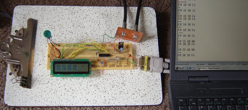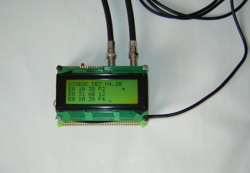

| The breadboarded circuit above is a simple Diseqc decoder / display with TTL serial data out. It's simple and robust enough circuit to build and experiment with on a breadboard, but I recommend soldered construction if you plan to use the circuit. The data displayed is the native hexadecimal requiring a lookup. Normally, there will only be a handful of different sentences. This can vary, depending on how many Diseqc devices your receiver talks to. |
The sentence with E0 31 6B 0D tells a diseqc positioner to move to satellite position #14.
The lower sentence E0 10 38 F6 is telling the switch to use port two. The star indicates the same command was heard more than once consecutively and the cursor indicates which line is newest. All the Diseqc documents are here. The bus specification is the reference I used. |
The decoder has only one control - a momentary switch for start/stop and hold 2 seconds for erase. It's powered by voltage on the coax, turning off and on with the receiver. A splash screen greets user at power up with version info. The serial output is 9600,8,1 and displays as shown. The download zip file contains the code, schematic and builder notes. |
 |
 |
| Today, a common problem for big dish users who've switched to digital is polarity control out at the feedhorn. This is because the older Corotor systems have a servo motor moving the receiving element inside the feedhorn to the proper angle. Unfortunately, the new receivers seldom support the Corotor type servo control. |
They switch polarity by changing the voltage on the coax. While you can get by using your old analog receiver for polarity control, it's cumbersome and requires you make two entries per band, one for each polarity. By incorporating a voltage operated servo controller, an old system will work in sync with a new receiver. |
To this end, I designed my own line powered polarity controller utilizing a PIC 16F716 micro. The PIC senses coax voltage and selects either vertical or horizontal range. Turning the rotary encoder knob allows up to 90 degrees of adustment within this range. The LCD display shows which polarity, the feed angle and coax volts. |
 |
 |
| This is the basic, no frills version of the coax sensing feed horn servo control. The PIC 12F683 allows for extra simplification due to it's aditional built in capabilities. This is the design I've been using for over a year on my own system. The red/green LED indication is an effective indication of voltage on the line as well as polarity sensed. The unit the photo is indicating vertical polarity meaning it sees about 13 volts and outputs the corresponding pulse width. |
 |
| Another device I created is the PIC operated Diseqc relay switch. My Ku dish mover draws too much current to use a standard diode operated switch. Instead, I use a 2A Panasonic latching relay to control the signal path between my C and Ku band dishes. . |
A PIC 12F629 8 pin micro handles the Diseqc decoding and logic output. This design is limited to two ports (#1 and #2). An audible "click" is heard upon each port change and the relay "remembers" the last direction when turned off. . |
While the relay is not rated for RF frequencies, I have not noticed any signal degradation. The 2.2 uH choke offers less than an ohm reactance at 22 KHz signal freq and over 13k at 950 MHz, effectively separating the signals. . |
 |
 |
 |
This page last updated 12-31-2012