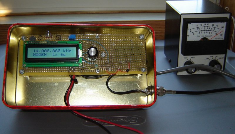
The finished project mounted in a cookie tin and transmitting a bit over 100 mW on 20 meters
|
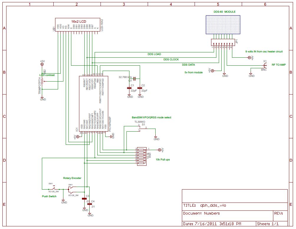
The signal is synthesized on a DDS-60 kit from Midnight Design and tuned by a PIC 16F628A micro. The program software is written in assembly language and the file pack also contains the .hex file. The synthesizer control routines are from WB2V, AA0ED, AA0ZZ and have been modified to work with the DDS-60 and the newer PIC. The QRSS mode and it's configure routine are my own. A rotary encoder and ON-OFF-ON switch are the user interface which allow for callsign entry, calibration, QRSS on/off and band switch. The 16x2 LCD display provides frequency to 1 Hz resolution and feed back varying with the mode selected. |
While many QRSS enthusiasts have incorporated a GPS time base for accuracy, I decided to take a more minimalist approach. My time base is a 10 ppm, 32.768 kHz tuning fork clock which increments a 16 bit counter on the PIC micro. As a result, the PIC has a slow, accurate time base, yet still processes everything at it's internal oscillator speed of 4 MHz. In QRSS mode, the characters are exactly 6 or 18 seconds in length and the string is repeated precisely every 10 minutes. |
Changing the call is as easy as holding the encoder switch while turning it on. Release and turn the knob to cycle through the alphabet and numbers, pressing it to select displayed character.
When you have it right, select star(*) to save and exit. Because it's stored in non volatile memory, the unit will retain the data until you decide to change it.. In order to create the Morse characters, the beacon program has a built in ASCII text to Morse converter. At startup, the program reads and converts the callsign in EE memory to a Morse string and stores it for use in QRSS mode. |
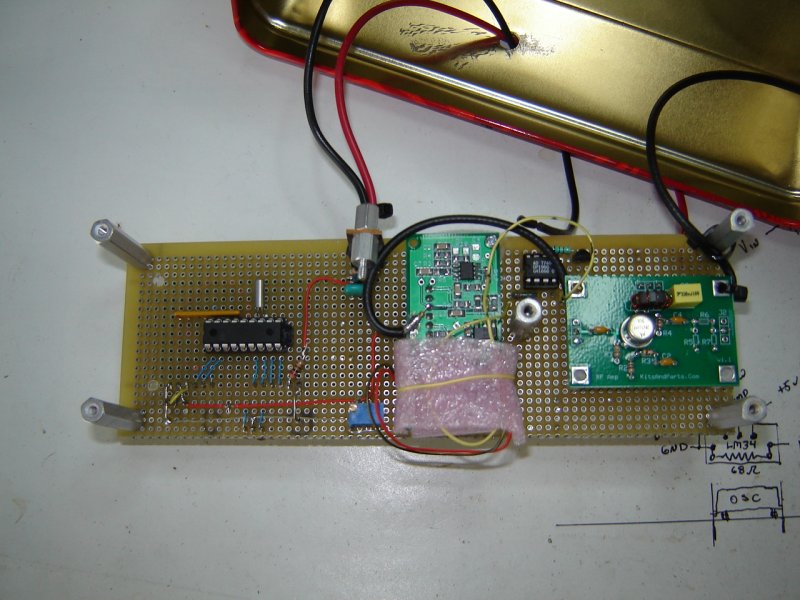
A couple of kits brought together by this project.
The $8 DIZ 20 db hf amp on the right.
Center is the $50 DDS-60 kit
Left is the micro controller, a PIC 16F628A in a socket with the 32.768 kHz crystal above.
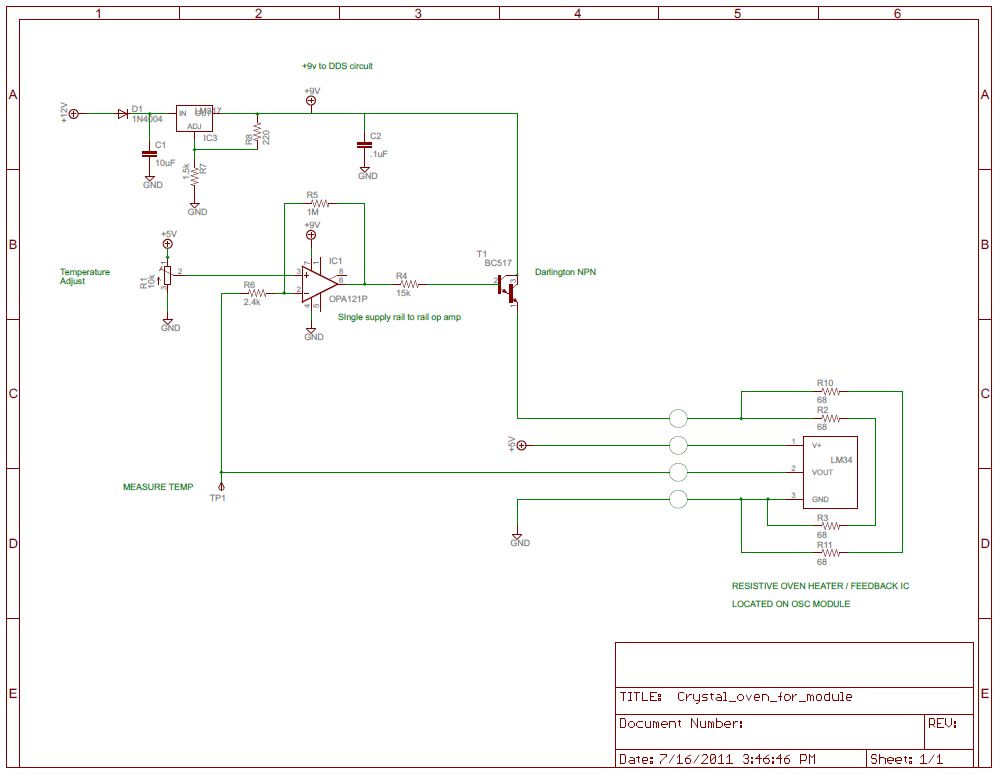
The 8 pin socketed IC between the DDS and amp is the oven temperature control op amp.
Next to the right is the oven heater darlington transistor controlled by the op amp.
The DDS-60 module supplies the +5 volts to the PIC, LCD and part of the oven circuit.
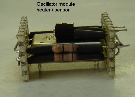
The heater upsized for a full size oscillator module. |
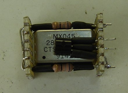
Connections to the control circuitry are made from right hand pcb |
Oscillator oven and power supply circuit (click for larger image). |
The control and display circuitry for the DDS-60 (click for larger image). |
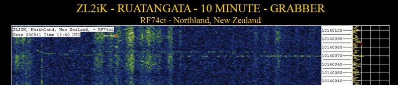
This is the received signal in New Zealand - grabbed and served on the Internet.
Here's the same transmission copied in Florida..
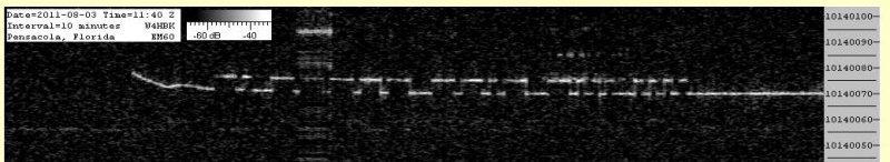
Note the "hook" at the beginning - the oven circuit was just getting to temperature.
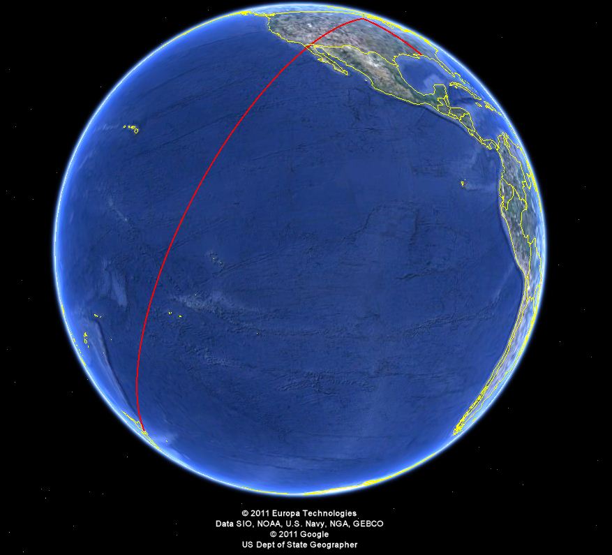
The two paths signals took in the above examples.
Download the N0QBH DDS-60 QRSS project
This page was updated 9-17-2011